GEF常见问题8:导出到图片

利用org.eclipse.draw2d.SWTGraphics类和org.eclipse.swt.graphics.ImageLoader类可以实现把画布导出到图片文件的功能,原理是在内存里创建一个空白的Image,然后把Diagram画到它上面,最后保存到指定文件和格式。

我们可以把导出工作分为两部分,第一部分负责提供要导出的IFigure实例(若要导出整个画布,应从GraphicalViewer获得PRINTABLE_LAYERS,否则会丢失画布上的连线),并负责将得到的图片数据写入文件;第二部分负责IFigure实例到图片数据的转换过程。以下是前者的示例代码:

String filename = ...;
PracticeEditor editor = ...;
ScalableFreeformRootEditPart rootPart = ...;
IFigure figure = rootPart.getLayer(ScalableFreeformRootEditPart.PRINTABLE_LAYERS);//To ensure every graphical element is included
byte[] data = createImage(figure, SWT.IMAGE_PNG);
try {
    FileOutputStream fos = new FileOutputStream(filename);
    fos.write(data);
    fos.close();
} catch (IOException e) {
    e.printStackTrace();
}

上面代码里调用的createImage()方法是实际在内存里作画并转换为可写入为文件的二进制流的地方,代码如下所示:

private byte[] createImage(IFigure figure, int format) {
    Rectangle r = figure.getBounds();
    ByteArrayOutputStream result = new ByteArrayOutputStream();
    Image image = null;
    GC gc = null;
    Graphics g = null;
    try {
        image = new Image(null, r.width, r.height);
        gc = new GC(image);
        g = new SWTGraphics(gc);
        g.translate(r.x * -1, r.y * -1);
        figure.paint(g);
        ImageLoader imageLoader = new ImageLoader();
        imageLoader.data = new ImageData[] { image.getImageData() };
        imageLoader.save(result, format);
    } finally {
        if (g != null) {
            g.dispose();
        }
        if (gc != null) {
            gc.dispose();
        }
        if (image != null) {
            image.dispose();
        }
    }
    return result.toByteArray();
}

点此下载工程,此工程修改自GEF应用实例中的GefPractice,目标文件的扩展名为.gefpractice不变。

file
图1 运行后增加了导出功能按钮

参考资料

GEF新闻组里相关链接:
http://dev.eclipse.org/newslists/news.eclipse.tools.gef/msg05012.html
http://dev.eclipse.org/newslists/news.eclipse.tools.gef/msg06329.html

搬家前链接:https://www.cnblogs.com/bjzhanghao/archive/2007/08/01/838278.html

[Eclipse]GEF入门系列(十二、自定义Request)

先简单回顾一下Request在GEF里的作用。Request是GEF里一个比较重要的角色,Tool将原始的鼠标事件转换为EditPart可以识别的请求,Request则承载了这些请求信息。举例来说,用户在调色板(Palette)里选择了创建节点工具(CreationTool),然后在画布区域按下鼠标左键,这时产生在画布上的鼠标单击事件将被CreationTool转换为一个CreateRequest,它里面包含了要创建的对象,坐标位置等信息。 EditPart上如果安装了能够处理CreateRequest的EditPolicy,则相应的EditPolicy会根据这个 CreateRequest创建一个Command,由后者实际执行创建新对象的必要操作。

GEF已经为我们提供了很多种类的Request,其中最常用的是CreateRequest及其子类 CreateConnectionRequest,其他比较常见的还有SelectionRequest,ChangeBoundsRequest和 ReconnectRequest等等。要实现一个典型的图形化应用程序,例如UML类图编辑器,这些预定义的Request基本够用了。然而各种稀奇古怪的需求我相信大家也见过不少,很多需求不太符合约定俗成的使用习惯,因此实现起来更多依赖开发人员的编码,而不是开发框架带来的便利。在这种时候,我们唯一的期望就是开发框架提供足够的扩展机制,以便让我们额外编写的代码能和其他代码和平共处,幸好GEF是具有足够的扩展性的。

再回到Request的问题上,为了说明什么情况下需要自定义Request,我在前文“应用实例”里的示例应用基础上假设一个新的需求:

在Palette里增加三个工具,作用分别是把选中节点的背景颜色改变为红色、绿色和蓝色。

假如你用过Photoshop或类似软件,这个需求很像给节点上色的“油漆桶”或“上色工具”,当然在用户界面的背后,实际应用里这些颜色可能代表一个节点的重要程度,优先级或是异常信息等等。现在,让我们通过创建一个自定义的Request来实现这个需求,还是以前文中的示例项目为基础。

一、首先,原来的模型里节点(Node)类里没有反映颜色的成员变量,所以先要在Node类里添加一个color属性,以及相应的 getter/setter方法,注意这个setter方法里要和其他成员变量的setter方法一样传递模型改变的消息。仿照其他成员变量,还应该有一个静态字符串变量,用来区分消息对应哪个属性。

final public static String PROP_COLOR = "COLOR";

protected RGB color = new RGB(255, 255, 255);

public RGB getColor() {
    return color;
}

public void setColor(RGB color) {
    if (this.color.equals(color)) {
        return;
    }
    this.color = color;
    firePropertyChange(PROP_COLOR, null, color);
}

二、然后,要让Node的color属性变化能够反映到图形上,因此要修改NodePart里的propertyChanged()和 refreshVisuals()方法,在前者里增加对color属性的响应,在后者里将NodeFigure的背景颜色设置为Node的color属性对应的颜色。(注意,Color对象是系统资源对象,实际使用里需要缓存以避免系统资源耗尽,为节约篇幅起见,示例代码直接new Color()了)

public void propertyChange(PropertyChangeEvent evt) {

    if (evt.getPropertyName().equals(Node.PROP_COLOR))//Response to color change
        refreshVisuals();
}

protected void refreshVisuals() {

    ((NodeFigure) this.getFigure()).setBackgroundColor(new Color(null, node.getColor()));//TODO cache color instances
}

三、现在来创建我们自己的Request,因为目的是改变颜色,所以不妨叫做ChangeColorRequest。它应当继承自org.eclipse.gef.Request,我们需要ChangeColorRequest上带有两样信息:1.需要改变颜色的节点;2.目标颜色。因此它应该有这两个成员变量。

import org.eclipse.gef.Request;
import org.eclipse.swt.graphics.RGB;
import com.example.model.Node;

public class ChangeColorRequest extends Request{
    final static public String REQ_CHANGE_COLOR="REQ_CHANGE_COLOR";
    private Node node;
    private RGB color;

    public ChangeColorRequest(Node node, RGB color) {
        super();
        this.color = color;
        this.node = node;
        setType(REQ_CHANGE_COLOR);
    }

    public RGB getColor() {
        return color;
    }

    public Node getNode() {
        return node;
    }

    public void setNode(Node node) {
        this.node = node;
    }

    public void setColor(RGB color) {
        this.color = color;
    }

}

ChangeColorRequest看起来和一个JavaBean差不多,的确如此,因为Request的作用就是传递翻译后的鼠标事件。如果你看一下org.eclipse.gef.Request的代码,你会发现Request还有一个type属性,这个属性一般是一个字符串(在gef的RequestConstants里预定义了一些,如RequestConstants.REQ_SELECTION_HOVER),EditPolicy可以根据它决定是否处理这个Request。在我们的例子里,顺便定义了这样一个常量字符串REQ_CHANGE_COLOR,在后面的 ChangeColorEditPolicy里会用到它。

四、现在有一个问题,这个Request的实例应该在哪里生成?答案是在Tool里,用户在画布区域按下鼠标左键时,当前 Palette里被选中的Tool负责创建一个Request。我们现在面对的这个需求需要我们创建一种新的Tool:ChangeColorTool。我们让ChangeColorTool继承org.eclipse.gef.tools.SelectionTool,因为“上色工具”的用法和“选择工具”基本上差不多。显然,我们需要覆盖的是handleButtonDown()方法,用来告诉gef如果用户当前选择了这个工具,在画布区域按下鼠标会发生什么事情。代码如下:

import org.eclipse.gef.EditPart;
import org.eclipse.gef.commands.Command;
import org.eclipse.gef.tools.SelectionTool;
import org.eclipse.swt.graphics.RGB;
import com.example.model.Node;
import com.example.parts.NodePart;

public class ChangeColorTool extends SelectionTool {
    private RGB color;

    public ChangeColorTool(RGB color) {
        super();
        this.color = color;
    }

    /**
     * If target editpart is an {@link NodePart}, create a {@link ChangeColorRequest} instance, 
     * get command from target editpart with this request and execute.
     */
    @Override
    protected boolean handleButtonDown(int button) {
        //Get selected editpart
        EditPart editPart = this.getTargetEditPart();

        if (editPart instanceof NodePart) {
            NodePart nodePart = (NodePart) editPart;
            Node node = (Node) nodePart.getModel();

            //Create an instance of ChangeColorRequest
            ChangeColorRequest request = new ChangeColorRequest(node, color);

            //Get command from the editpart
            Command command = editPart.getCommand(request);

            //Execute the command
            this.getDomain().getCommandStack().execute(command);

            return true;
        }
        return false;
    }

}

五、有了Tool,还需要用ToolEntry把它包装起来添加到Palette里。所以我们创建一个名为 ChangeColorToolEntry并继承org.eclipse.gef.palette.ToolEntry的类,覆盖createTool()方法,让它返回我们的ChangeColorTool实例。这个ChangeColorToolEntry代码应该很容易理解:

import org.eclipse.gef.SharedCursors;
import org.eclipse.gef.Tool;
import org.eclipse.gef.palette.ToolEntry;
import org.eclipse.jface.resource.ImageDescriptor;
import org.eclipse.swt.graphics.RGB;

public class ChangeColorToolEntry extends ToolEntry {
    private RGB color;

    public ChangeColorToolEntry(RGB color, String label, String shortDesc, ImageDescriptor iconSmall,
            ImageDescriptor iconLarge) {
        super(label, shortDesc, iconSmall, iconLarge);
        this.color = color;
    }

    @Override
    public Tool createTool() {
        ChangeColorTool tool = new ChangeColorTool(color);
        tool.setUnloadWhenFinished(false);//Switch to selection tool after performed?
        tool.setDefaultCursor(SharedCursors.CROSS);//Any cursor you like
        return tool;
    }

}

六、要把三个这样的ToolEntry添加到Palette里,当然是通过修改原来的PaletteFactory类。为节约篇幅,这里就不帖它的代码了,可以下载并参考示例代码PaletteFactory.java里的createCategories()createColorDrawer()方法。

到目前为止,ChangeColorRequest已经可以发出了,接下来要解决的问题是如何让EditPart处理这个请求。

七、我们知道,GEF里任何对模型的修改都是通过command完成的,因此定义一个ChangeColorCommand肯定是需要的。它的execute()方法和undo()方法如下所示:

public class ChangeColorCommand extends Command{

    private RGB oldColor;

    @Override
    public void execute() {
        oldColor = node.getColor();
        node.setColor(color);
    }

    @Override
    public void undo() {
        node.setColor(oldColor);
    }
}

八、EditPolicy负责接收所有的Request,所以还要创建一个ChangeColorEditPolicy。在下面列出的代码里,你会看到我们定义了一个新的Role字符串,过一会儿我们在EditPart上安装这个EditPolicy的时候要以这个字符串作为Key,以避免覆盖EditPart上已有的其他EditPolicy。

import org.eclipse.gef.Request;
import org.eclipse.gef.commands.Command;
import org.eclipse.gef.editpolicies.AbstractEditPolicy;
import org.eclipse.swt.graphics.RGB;

import com.example.model.Node;

public class ChangeColorEditPolicy extends AbstractEditPolicy {
    final static public String CHANGE_COLOR_ROLE = "CHANGE_COLOR_ROLE";

    @Override
    public Command getCommand(Request request) {
        //Judge whether this request is intersting by its type
        if (request.getType() == ChangeColorRequest.REQ_CHANGE_COLOR) {
            ChangeColorRequest theRequest = (ChangeColorRequest) request;

            //Get information from request
            Node node = theRequest.getNode();
            RGB color = theRequest.getColor();

            //Create corresponding command and return it
            ChangeColorCommand command = new ChangeColorCommand(node, color);
            return command;
        }
        return null;
    }
}

九、最后还是回到EditPart,前面在第二个步骤里我们曾经修改过的NodePart里还有最后一处需要添加,那就是在installEditPolicies()方法里添加刚刚创建的ChangeColorEditPolicy:

protected void createEditPolicies() {

    //Add change color editpolicy
    installEditPolicy(ChangeColorEditPolicy.CHANGE_COLOR_ROLE, new ChangeColorEditPolicy());
}

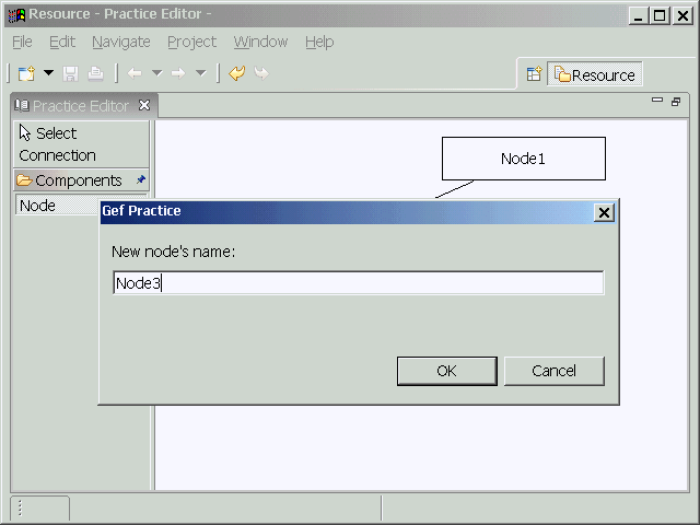
现在我们已经完成了所有必要的修改,来看一下运行结果。

file

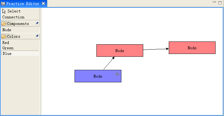
总结一下,需要创建的类有:ChangeColorRequest, ChangeColorTool, ChangeColorToolEntry, ChangeColorCommand, ChangeColorEditPolicy;需要修改的类有:Node, NodePart, PaletteFactory。在实例项目里,为了方便大家浏览,所有新创建的类都放在com.example.request包里,实际项目里还是建议分别放在对应的包里。

下载示例代码(在eclipse3.2.1和gef3.2下编译通过)

搬家前链接:https://www.cnblogs.com/bjzhanghao/archive/2007/06/21/792446.html

GEF常见问题7:计算字符串在画布上占据的空间

要准确的计算文字在画布上占据的空间,可以利用org.eclipse.swt.graphics.GC的stringExtent()方法实现,见下面的代码:

GC gc = new GC(Display.getDefault());
gc.setFont(yourFont);//这一步不可缺少,因为有些字体里各字符的宽度是不同的
Point size = gc.stringExtent(text);//得到文字占据的尺寸
label.setPreferredSize(size.x + 16, size.y + 10);//让标签的尺寸比文字稍大
gc.dispose();

运行时的效果:

file

搬家前链接:https://www.cnblogs.com/bjzhanghao/archive/2007/04/14/712794.html

关于Draw2D里的Layout

就像在swt里我们使用layout来控制各个控件的摆放位置一样,在Draw2D里最好也把这个工作交给LayoutManager来做。除非是在自己实现的Layout里,一般程序里自己不要轻易使用setBounds()setLocation()setSize()这些方法控制图形的位置和大小,而应该在为每个图形设置了适当的LayoutManager后,通过setConstraint()setPreferredSize()等方法告诉layoutmanager如何布局。

在需要的时候,父图形的布局管理器负责修改每个子图形的位置和大小,但计算每个子图形大小的工作可能是交给子图形自己的LayoutManager来做的,计算的方法一般是在这个LayoutManager的getPreferredSize()方法里体现。

例如当父图形使用XYLayout,子图形使用ToolbarLayout时,假设在子图形里又增加了子子图形(子图形里的子图形),add()方法会导致revalidate()的调用,这时父图形的xylayout将检查子图形是否具有constraint,如果有并且有至少一个方向为-1,则利用子图形上的ToolbarLayout计算出子图形新的尺寸,这个尺寸是和子图形里包含的子子图形的数目有关的(ToolbarLayout会把每个子图形的宽/高度加起来,加上其中间隔的空间,再考虑图形的边框,返回得到的尺寸)。

XYLayout对layout(IFigure)方法的实现:

public void layout(IFigure parent) {
    Iterator children = parent.getChildren().iterator();
    Point offset = getOrigin(parent);
    IFigure f;
    while (children.hasNext()) {
        f = (IFigure)children.next();
        Rectangle bounds = (Rectangle)getConstraint(f);//因此必须为子图形指定constraint
        if (bounds == null) continue;

        if (bounds.width == -1 || bounds.height == -1) {
            Dimension preferredSize = f.getPreferredSize(bounds.width, bounds.height);
            bounds = bounds.getCopy();
            if (bounds.width == -1)
                bounds.width = preferredSize.width;
            if (bounds.height == -1)
                bounds.height = preferredSize.height;
        }
        bounds = bounds.getTranslated(offset);
        f.setBounds(bounds);
    }
}

Draw2D里Figure类的setPreferredSize(Dimension)setSize(Dimension)的区别是,setSize()方法不会调用revalidate()方法导致重新layout,而只是调用repaint()对所涉及到的“脏”区域进行重绘(repaint)。setPreferredSize()方法可以约等于setSize()方法+revalidate()方法,因为在Figure对getPreferredSize(int,int)的实现里,若该figure没有任何layoutmanager,则返回当前size:

public Dimension getPreferredSize(int wHint, int hHint) {
    if (prefSize != null)
        return prefSize;
    if (getLayoutManager() != null) {
        Dimension d = getLayoutManager().getPreferredSize(this, wHint, hHint);
        if (d != null)
            return d;
    }
    return getSize();
}

只要看一下ToolbarLayout.java就会知道,ToolbarLayout对constraint是不感兴趣的,调用它的getConstraint()永远返回null值,所以我们不必对放在使用ToolbarLayout的图形的子图形设置constraint。因此,假如我们的问题是,有图形A包含B,B包含C,要实现B(使用ToolbarLayout)尺寸随C数目多少而自动改变该如何做呢?这要看A使用何种LayoutManager,如果是ToolbarLayout则不用做特殊的设置,如果是XYLayout则要用A.getLayoutManager().setConstraint(B,new Rectangle(x,y,-1,-1))这样的语句为A设置constraint,对图形C则用setPreferredSize()指定实际大小。

一个Layout的例子,点此下载,截图如下。

file

搬家前链接:https://www.cnblogs.com/bjzhanghao/archive/2006/09/05/495747.html

GEF常见问题6:使用对话框

除了利用Eclipse提供的属性视图以外,GEF应用程序里当然也可以通过弹出对话框修改模型信息。

要实现双击一个节点打开对话框,在NodePart里要增加的代码如下:

public void performRequest(Request req) {
    if(req.getType().equals(RequestConstants.REQ_OPEN)){
        MessageDialog.openInformation(getViewer().getControl().getShell(),"Gef Practice","A Dialog");
    }
}

作为例子,上面这段代码只打开一个显示信息的对话框,你可以替换成自己实现的对话框显示/修改节点信息。

在CreateNodeCommand里增加下面的代码,可以在每次创建一个节点时通过对话框指定节点的名称:

public void execute() {
    InputDialog dlg = new InputDialog(shell, "Gef Practice", "New node's name:", "Node", null);
    if (Window.OK == dlg.open()) {
        this.node.setName(dlg.getValue());
    }
    this.diagram.addNode(this.node);
}

因为打开对话框时需要用到Shell,所以要在CreateNodeCommand里增加一个Shell类型的成员变量,并在DiagramLayoutEditPolicy里创建CreateNodeCommand时把一个shell实例传递给它。

file
创建节点时先弹出对话框

代码下载

点此下载工程,此工程修改自GEF应用实例中的GefPractice,目标文件的扩展名改为.gefpracticedlg。

搬家前链接:https://www.cnblogs.com/bjzhanghao/archive/2006/07/07/445603.html

GEF常见问题5:自动布局

利用自动布局功能,我们可以把本来不包含图形信息的文件以图形化的方式展示出来,典型的例子比如将一组Java接口反向工程为类图,那么图中每个图元的坐标应该必须都是自动生成的。GEF里提供了DirectedGraphLayout类用来实现自动布局功能,下面介绍一下怎样在程序里使用它。

DirectedGraphLayout提供的visit()方法接受一个org.eclipse.draw2d.graph.DirectedGraph实例,它遍历这个有向图的所有节点和边,并按照它自己的算法计算出每个节点布局后的新位置。所以在使用它布局画布上的图元分为两个步骤:1、构造有向图,2、将布局信息应用到图元。

还是以gefpractice为基础,我们在主工具条上增加了一个自动布局按钮,当用户按下它时自动布局编辑器里的图形,再次按下时恢复以前的布局。为了完成步骤1,我们要在DiagramPart里添加以下两个方法:

/**
 * 将图元(NodePart)转换为节点(Node)到有向图
 * @param graph
 * @param map
 */
public void contributeNodesToGraph(DirectedGraph graph, Map map) {
    for (int i = 0; i < getChildren().size(); i++) {
        NodePart node = (NodePart)getChildren().get(i);
        org.eclipse.draw2d.graph.Node n = new org.eclipse.draw2d.graph.Node(node);
        n.width = node.getFigure().getPreferredSize().width;
        n.height = node.getFigure().getPreferredSize().height;
        n.setPadding(new Insets(10,8,10,12));
        map.put(node, n);
        graph.nodes.add(n);
    }
}

/**
 * 将连接(ConnectionPart)转换为边(Edge)添加到有向图
 * @param graph
 * @param map
 */
public void contributeEdgesToGraph(DirectedGraph graph, Map map) {
    for (int i = 0; i < getChildren().size(); i++) {
        NodePart node = (NodePart)children.get(i);
        List outgoing = node.getSourceConnections();
        for (int j = 0; j < outgoing.size(); j++) {
            ConnectionPart conn = (ConnectionPart)outgoing.get(j);
            Node source = (Node)map.get(conn.getSource());
            Node target = (Node)map.get(conn.getTarget());
            Edge e = new Edge(conn, source, target);
            e.weight = 2;
            graph.edges.add(e);
            map.put(conn, e);
        }
    }
}

要实现步骤2,在DiagramPart里添加下面这个方法:

/**
 * 利用布局后的有向图里节点的位置信息重新定位画布上的图元
 * @param graph
 * @param map
 */
protected void applyGraphResults(DirectedGraph graph, Map map) {
    for (int i = 0; i < getChildren().size(); i++) {
        NodePart node = (NodePart)getChildren().get(i);
        Node n = (Node)map.get(node);
        node.getFigure().setBounds(new Rectangle(n.x, n.y, n.width, n.height));
    }
}

为了以最少的代码说明问题,上面的方法里只是简单的移动了图形,而没有改变模型里Node的属性值,在大多情况下这里使用一个CompoundCommand对模型进行修改更为合适,这样用户不仅可以撤消(Undo)这个自动布局操作,还可以在重新打开文件时看到关闭前的样子。注意,DirectedGraphLayout是不保证每次布局都得到完全相同的结果的。

因为Draw2D里是用LayoutManager管理布局的,而DirectedGraphLayout只是对布局算法的一个包装,所以我们还要创建一个布局类。GraphLayoutManager调用我们在上面已经添加的那几个方法生成有向图(partsToNodes变量维护了编辑器图元到有向图图元的映射),利用DirectedGraphLayout对这个有向图布局,再把结果应用到编辑器里图元。如下所示:

class GraphLayoutManager extends AbstractLayout {

    private DiagramPart diagram;

    GraphLayoutManager(DiagramPart diagram) {
        this.diagram = diagram;
    }

    protected Dimension calculatePreferredSize(IFigure container, int wHint, int hHint) {
        container.validate();
        List children = container.getChildren();
        Rectangle result = new Rectangle().setLocation(container.getClientArea().getLocation());
        for (int i = 0; i < children.size(); i++)
            result.union(((IFigure) children.get(i)).getBounds());
        result.resize(container.getInsets().getWidth(), container.getInsets().getHeight());
        return result.getSize();
    }

    public void layout(IFigure container) {
        DirectedGraph graph = new DirectedGraph();
        Map partsToNodes = new HashMap();
        diagram.contributeNodesToGraph(graph, partsToNodes);
        diagram.contributeEdgesToGraph(graph, partsToNodes);
        new DirectedGraphLayout().visit(graph);
        diagram.applyGraphResults(graph, partsToNodes);
    }

}

当用户按下自动布局按钮时,只要设置DiagramPart对应的图形的布局管理器为GraphLayoutManager就可以实现自动布局了,布局的结果如图所示。

file
自动布局的结果

最后有几点需要说明:

1、DirectedGraphLayout只能对连通的有向图进行布局,否则会产生异常graph is not fully connected,参考Eclipse.org文章Building a Database Schema Diagram Editor中使用的NodeJoiningDirectedGraphLayout可以解决这个问题;

2、如果要对具有嵌套关系的有向图自动布局,应使用SubGraphCompoundDirectedGraphLayout

3、这个版本的gefpractice在自动布局后,没有对连接线进行处理,所以可能会出现连接线穿过图元的情况,这个问题和上一个问题都可以参考GEF提供的flow例子解决。

Update(2007/4/9):如果diagram是放在ScrollPane里的,则要修改一下applyGraphResults()方法,增加container作为参数以使整个diagram能正确滚动。

protected void applyGraphResults(DirectedGraph graph, Map map, IFigure container) {
    for (Iterator iterator = this.nodeParts.iterator(); iterator.hasNext();) {
        NodePart element = (NodePart) iterator.next();
        Node n = (Node) map.get(element);
        Rectangle containerBounds=container.getBounds();
        Rectangle elementBounds=new Rectangle(n.x, n.y, n.width, n.height);
        element.getFigure().setBounds(elementBounds.translate(containerBounds.getLocation()));
    }
}

代码下载

点此下载工程,此工程修改自GEF应用实例中的GefPractice,目标文件的扩展名改为.gefpracticeal。

搬家前链接:https://www.cnblogs.com/bjzhanghao/archive/2006/07/02/440896.html

GEF常见问题4:非矩形图元

现在假设要把原来GefPractice例子里的矩形图元节点换成用椭圆形表示,都需要做哪些改动呢?很显然,首先要把原来继承RectangleFigure的NodeFigure类改为继承Ellipse类:

public class NodeFigure extends Ellipse {
    ...
}

这样修改后可以看到编辑器中的图元已经变成椭圆形了。但如果用户点选一个图元,表示选中的边框(选择框)仍然是矩形的,如图1所示:

file
图1 椭圆形的节点和矩形选择框

如果觉得矩形的选择框不太协调,可以通过覆盖DiagramLayoutEditPolicy的createChildEditPolicy()方法修改。缺省情况下这个方法返回一个ResizableEditPolicy,我们要定义自己的子类(EllipseResizableEditPolicy)来替代它作为返回值。

EllipseResizableEditPolicy里需要覆盖ResizableEditPolicy的两个方法。第一个是createSelectionHandles()方法,它决定“控制柄”(ResizeHandle)和“选择框”(MoveHandle)的相关情况,我们的实现如下:

protected List createSelectionHandles() {
    List list = new ArrayList();
    //添加选择框
    //ResizableHandleKit.addMoveHandle((GraphicalEditPart) getHost(), list);
    list.add(new MoveHandle((GraphicalEditPart) getHost()) {
        protected void initialize() {
            super.initialize();
            setBorder(new LineBorder(1) {
                public void paint(IFigure figure, Graphics graphics, Insets insets) {
                    tempRect.setBounds(getPaintRectangle(figure, insets));
                    if (getWidth() % 2 == 1) {
                        tempRect.width--;
                        tempRect.height--;
                    }
                    tempRect.shrink(getWidth() / 2, getWidth() / 2);
                    graphics.setLineWidth(getWidth());
                    if (getColor() != null)
                        graphics.setForegroundColor(getColor());
                    //用椭圆形替代矩形
                    //graphics.drawRectangle(tempRect);
                    graphics.drawOval(tempRect);
                }
            });
        }
    });

    //添加控制柄
    ResizableHandleKit.addHandle((GraphicalEditPart) getHost(), list, PositionConstants.EAST);
    ResizableHandleKit.addHandle((GraphicalEditPart) getHost(), list, PositionConstants.SOUTH);
    ResizableHandleKit.addHandle((GraphicalEditPart) getHost(), list, PositionConstants.WEST);
    ResizableHandleKit.addHandle((GraphicalEditPart) getHost(), list, PositionConstants.NORTH);
    return list;
}

第二个是createDragSourceFeedbackFigure()方法,它决定用户拖动图形时,随鼠标移动的半透明图形(即“鬼影”)的形状和颜色,因此我们覆盖这个方法以显示椭圆形的鬼影。

protected IFigure createDragSourceFeedbackFigure() {
    //用椭圆替代矩形
    //RectangleFigure r = new RectangleFigure();
    Ellipse r = new Ellipse();
    FigureUtilities.makeGhostShape(r);
    r.setLineStyle(Graphics.LINE_DOT);
    r.setForegroundColor(ColorConstants.white);
    r.setBounds(getInitialFeedbackBounds());
    addFeedback(r);
    return r;
}

经过以上这些修改,可以看到选择框和鬼影都是椭圆的了,如图2所示。

file
图2 与节点形状相同的选择框和鬼影

代码下载

点此下载工程,此工程修改自GEF应用实例中的GefPractice,目标文件的扩展名改为.gefpracticeel。

搬家前链接:https://www.cnblogs.com/bjzhanghao/archive/2006/06/26/436455.html

GEF常见问题3:自身连接

在类图里能看到一些对象具有对自己的引用,通常这些引用用于表达树状结构,即父子节点都是同一类对象。用GEF绘制这样的连接线一般是通过转折点(Bendpoint)实现的,如果你的GEF应用程序里还不能使用Bendpoint,请按照上一篇介绍的步骤添加对Bendpoint的支持。

原先我们的GefPractice应用程序是不允许一条连接线的起点和终点都是同一个图形的,因为这样会导致连接线缩成一个点隐藏在图形下方,用户并不知道它的存在。当时我们在CreateConnectionCommand类的canExecute()方法里进行了如下判断:

public boolean canExecute() {
    if (source.equals(target))
        return false;
    ...
}

因此现在首先要把这两句删除。然后在execute()方法里对自身连接的这种情况稍做处理,处理的方法是给这条连接线在适当位置增加三个Bendpoint,你也可以根据想要的连接线形状修改Bendpoint的数目和位置。

public void execute() {
    connection = new Connection(source, target);
    if (source == target) {
        //The start and end points of our connection are both at the center of the rectangle,
        //so the two relative dimensions are equal.
        ConnectionBendpoint cbp = new ConnectionBendpoint();
        cbp.setRelativeDimensions(new Dimension(0, -60), new Dimension(0, -60));
        connection.addBendpoint(0, cbp);
        ConnectionBendpoint cbp2 = new ConnectionBendpoint();
        cbp2.setRelativeDimensions(new Dimension(100, -60), new Dimension(100, -60));
        connection.addBendpoint(1, cbp2);
        ConnectionBendpoint cbp3 = new ConnectionBendpoint();
        cbp3.setRelativeDimensions(new Dimension(100, 0), new Dimension(100, 0));
        connection.addBendpoint(2, cbp3);
    }
}

现在用户只要选择连接工具,然后在一个节点上连续点两下就可以创建自身连接了,如下图所示。

file
图:自身连接

代码下载

点此下载工程,此工程修改自GEF常见问题2中的GefPractice-bp,目标文件扩展名为.gefpracticesc。

搬家前链接:https://www.cnblogs.com/bjzhanghao/archive/2006/06/22/432553.html

GEF常见问题2:具有转折点的连接线

从直线连接转换到可以任意增减转折点的折线连接,因为模型里要增加新的元素,所以模型、editpart和图形部分都要有所修改,显得稍微有些烦琐,但其实很多代码是通用的。这个过程主要分为以下几个部分:

1、在模型里增加转折点对应的类(这些转折点在GEF里称作Bendpoint),在类里要具有两个Dimension类型用来记录Bendpoint相对连接线起止点的位置。在连接类里要维护一个Bendpoint列表,并提供访问方法,由于篇幅关系这里只列出连接类中的这几个方法。

public void addBendpoint(int index, ConnectionBendpoint point) {
    getBendpoints().add(index, point);
    firePropertyChange(PROP_BENDPOINT, null, null);
}

/**
 * zhanghao: 为了在更新两个dimension后能发送事件,在MoveBendpointCommand要在用这个方法设置新坐标,
 * 而不是直接用BendPoint里的方法。
 */
public void setBendpointRelativeDimensions(int index, Dimension d1, Dimension d2){
    ConnectionBendpoint cbp=(ConnectionBendpoint)getBendpoints().get(index);
    cbp.setRelativeDimensions(d1,d2);
    firePropertyChange(PROP_BENDPOINT, null, null);
}

public void removeBendpoint(int index) {
    getBendpoints().remove(index);
    firePropertyChange(PROP_BENDPOINT, null, null);
}

2、在原来的连接方式里,由于连接线本身不需要刷新,所以现在要确保这个editpart实现了PropertyChangeListener接口,并像其他editpart一样覆盖了activate()deactivate()这两个方法,以便接收Bendpoint发生改变的事件。

public void activate() {
    super.activate();
    ((Connection)getModel()).addPropertyChangeListener(this);
}

public void deactivate() {
    super.deactivate();
    ((Connection)getModel()).removePropertyChangeListener(this);
}

public void propertyChange(PropertyChangeEvent event) {
    String property = event.getPropertyName();
    if(Connection.PROP_BENDPOINT.equals(property)){
        refreshBendpoints();
    }
}

为模型连接类对应的editpart里增加一个继承自BendpointEditPolicy的子类ConnectionBendPointEditPolicy,这个类的内容后面会说到。

protected void createEditPolicies() {
    ...
    installEditPolicy(EditPolicy.CONNECTION_BENDPOINTS_ROLE, new ConnectionBendPointEditPolicy());

直线连接的情况下,连接的刷新不需要我们负责,但增加了Bendpoint以后,必须在Bendpoint发生改变时刷新连接线的显示。所以在上面这个editpart的refreshVisuals()方法里需要增加一些代码,以便把模型里的Bendpoint转换为图形上的relativeBendpoint。

protected void refreshVisuals() {
    Connection conn = (Connection) getModel();
    List modelConstraint = conn.getBendpoints();
    List figureConstraint = new ArrayList();
    for (int i = 0; i < modelConstraint.size(); i++) {
        ConnectionBendpoint cbp = (ConnectionBendpoint) modelConstraint
                .get(i);
        RelativeBendpoint rbp = new RelativeBendpoint(getConnectionFigure());
        rbp.setRelativeDimensions(cbp.getFirstRelativeDimension(), cbp
                .getSecondRelativeDimension());
        rbp.setWeight((i + 1) / ((float) modelConstraint.size() + 1));
        figureConstraint.add(rbp);
    }
    getConnectionFigure().setRoutingConstraint(figureConstraint);
}

3、创建CreateBendpointCommand、MoveBendpointCommand和DeleteBendpointCommand这三个类,可以像Logic例子那样创建一个基类BendPointCommand让它们来继承。作为例子,BendpointCommand的内容如下。

public class BendpointCommand extends Command {

    protected int index;
    protected Connection connection;
    protected Dimension d1, d2;

    public void setConnection(Connection connection) {
        this.connection = connection;
    }

    public void redo() {
        execute();
    }

    public void setRelativeDimensions(Dimension dim1, Dimension dim2) {
        d1 = dim1;
        d2 = dim2;
    }

    public void setIndex(int i) {
        index = i;
    }
}

4、在ConnectionBendPointEditPolicy里实现BendpointEditPolicy定义的创建、移动和删除Bendpoint的三个方法。

public class ConnectionBendPointEditPolicy extends BendpointEditPolicy {

    protected Command getCreateBendpointCommand(BendpointRequest request) {
        CreateBendpointCommand cmd = new CreateBendpointCommand();
        Point p = request.getLocation();
        Connection conn = getConnection();

        conn.translateToRelative(p);

        Point ref1 = getConnection().getSourceAnchor().getReferencePoint();
        Point ref2 = getConnection().getTargetAnchor().getReferencePoint();

        conn.translateToRelative(ref1);
        conn.translateToRelative(ref2);

        cmd.setRelativeDimensions(p.getDifference(ref1), p.getDifference(ref2));
        cmd.setConnection((com.example.model.Connection) request.getSource()
                .getModel());
        cmd.setIndex(request.getIndex());
        return cmd;
    }

    protected Command getDeleteBendpointCommand(BendpointRequest request) {
        BendpointCommand cmd = new DeleteBendpointCommand();
        Point p = request.getLocation();
        cmd.setConnection((com.example.model.Connection) request.getSource().getModel());
        cmd.setIndex(request.getIndex());
        return cmd;
    }

    protected Command getMoveBendpointCommand(BendpointRequest request) {
        MoveBendpointCommand cmd = new MoveBendpointCommand();
        Point p = request.getLocation();
        Connection conn = getConnection();

        conn.translateToRelative(p);

        Point ref1 = getConnection().getSourceAnchor().getReferencePoint();
        Point ref2 = getConnection().getTargetAnchor().getReferencePoint();

        conn.translateToRelative(ref1);
        conn.translateToRelative(ref2);

        cmd.setRelativeDimensions(p.getDifference(ref1), p.getDifference(ref2));
        cmd.setConnection((com.example.model.Connection) request.getSource()
                .getModel());
        cmd.setIndex(request.getIndex());
        return cmd;
    }
}

修改完成后的编辑器如下图所示。

file
图:编辑器中的转折连接线

代码下载

点此下载工程,此工程修改自GEF应用实例中的GefPractice,目标文件的扩展名改为.gefpracticebp。

搬家前链接:https://www.cnblogs.com/bjzhanghao/archive/2006/06/22/432227.html