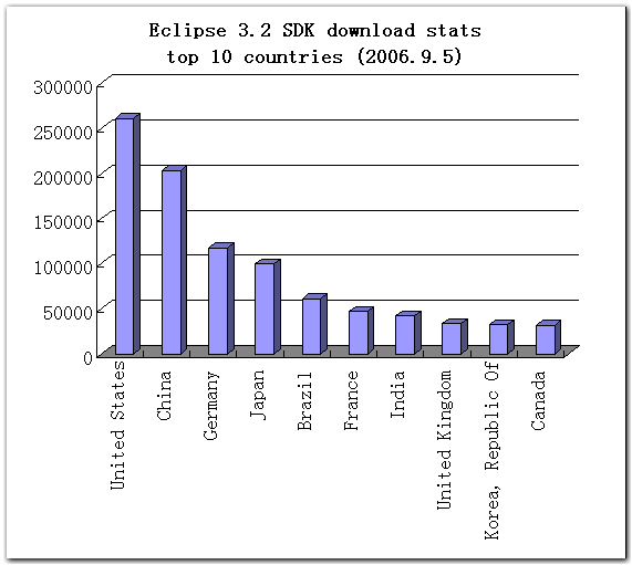
这是截至2006年9月初的数据,Eclipse 3.2下载总量约为128万份,原文在此。
搬家前链接:https://www.cnblogs.com/bjzhanghao/archive/2006/09/12/501673.html
这是截至2006年9月初的数据,Eclipse 3.2下载总量约为128万份,原文在此。

搬家前链接:https://www.cnblogs.com/bjzhanghao/archive/2006/09/12/501673.html
假设GMF为你生成的项目名称为com.example.diagram,现在要在右键菜单里增加一个自定义命令,并关联在名为Activity的模型元素上,即只有在Activity类型的元素上点右键,弹出菜单里才有这个自定义命令。此命令的功能是简单的把该Activity的Name属性改为Modified Activity。实现的步骤如下:
1、如果之前没有创建过,则创建一个名为com.example.diagram.custom的plugin项目(以下简称为custom项目),新建这个项目的目的是把自己的定制与GMF生成的代码分开;
2、在custom项目里实现org.eclipse.ui.popupMenus扩展点,这样会在右键菜单里多出一个"Change"菜单项,下面有"Name"命令;
<extension
         point="org.eclipse.ui.popupMenus">
  <objectContribution
        adaptable="false"
        id="com.example.custom.objectContribution.ActivityEditPart"
        objectClass="com.example.diagram.edit.parts.ActivityEditPart">
     <menu
           id="BMAChange"
           label="&Change"
           path="additions">
        <separator name="group1"/>
     </menu>
     <action
           class="com.example.diagram.popup.ChangeActivityNameAction"
           enablesFor="1"
           id="com.example.diagram.popup.ChangeActivityNameAction"
           label="&Name"
           menubarPath="BMAChange/group1"/>
  </objectContribution>
</extension>3、实现上一步里定义的Action类ChangeActivityNameAction,这个类不仅要实现IObjectActionDelegate(popupMenus扩展点的要求),还要继承自AbstractActionDelegate这个类(GMF的要求)。我们要做的是实现doRun()方法,首先取得当前选中的editpart,然后创建一个SetRequest实例,它包含了改变属性操作的所有信息,包括目标对象、属性的名字和新属性值。因为GMF里editpart的getModel()方法不是业务模型里的元素了,而是View对象,要再调用View#getElement()才能得到业务模型里的元素,所以代码里我们利用ViewUtil#resolveSemanticElement()方法直接得到Activity对象。另外,GMF使用了EMFT的Transaction项目来操作模型,所以editpart.getEditingDomain()方法得到的会是一个TransactionalEditingDomain类型。
有了request,我们用它作为构造参数创建一个SetValueCommand(),这是一个GMF命令(实现org.eclipse.gmf.runtime.common.core.command.ICommand),用来改变属性值。最后要执行这个命令,我们知道command是要用CommandStack来执行的,这样才能undo/redo,但editpart.getDiagramEditDomain().getDiagramCommandStack()得到的CommandStack只能执行GEF的命令(org.eclipse.gef.commands.Command),所以要把我们的command用ICommandProxy()包装一下,这样就没问题了。
public class ChangeActivityNameAction extends AbstractActionDelegate
                implements IObjectActionDelegate {

    protected void doRun(IProgressMonitor progressMonitor) {

        // Get the selected edit part
        IStructuredSelection structuredSelection = getStructuredSelection();
        Object selection = structuredSelection.getFirstElement();
        IGraphicalEditPart editpart = (IGraphicalEditPart) selection;

        // Create a command to modify its property
        SetRequest request = new SetRequest(
                editpart.getEditingDomain(),
                ViewUtil.resolveSemanticElement((View) editpart.getModel()),//The semantic model
                BmaPackage.Literals.ACTIVITY__NAME,//Name feature of activity
                "Modified Activity");//New name value
        SetValueCommand command = new SetValueCommand(request);

        //Do the work
        editpart.getDiagramEditDomain().getDiagramCommandStack().execute(new ICommandProxy(command));

    }
}
Update: 可以用IGraphicalEditPart#resolveSemanticElement()直接取得editpart对应的EObject,IGraphicalEditPart#getNotationView()是得到View对象,和getModel()作用一样。
运行效果如下,选择修改名字命令后,Activity1的名字改为Modified Activity,并且可以undo/redo:

GMF提供的Logic例子中CreateLogicElementActionDelegate.java文件
GMF Tips,Change Names Of Newly Created Elements小节
GMF Tutorial Part 3
Update(2007/07/17): GMF更推荐使用IOperationHistory来修改模型,例如在Action的doRun()方法里像下面这样写:
AbstractTransactionalCommand command = new AbstractTransactionalCommand(
        editingDomain,
        "Modifying the model", Collections.EMPTY_LIST) {
    protected CommandResult doExecuteWithResult(
            IProgressMonitor monitor, IAdaptable info)
            throws ExecutionException {
        //在这里修改模型
        return CommandResult.newOKCommandResult();
    }
};
try {
    OperationHistoryFactory.getOperationHistory().execute(command,
            new SubProgressMonitor(progressMonitor, 1), null);
} catch (ExecutionException e) {
    MindmapDiagramEditorPlugin.getInstance().logError(
            "Unable to create model and diagram", e); //$NON-NLS-1$
}因为在GMF新闻组里提到过(原文链接):
in a GMF application, you should probably never execute commands in a CommandStack, because it will not be worth the effort of coordinating the IUndoContexts applied to these commands and your GMF AbstractTransactionalCommands to ensure that the Undo/Redo menus make sense.
搬家前链接:https://www.cnblogs.com/bjzhanghao/archive/2006/09/06/496394.html
就像在swt里我们使用layout来控制各个控件的摆放位置一样,在Draw2D里最好也把这个工作交给LayoutManager来做。除非是在自己实现的Layout里,一般程序里自己不要轻易使用setBounds()、setLocation()和setSize()这些方法控制图形的位置和大小,而应该在为每个图形设置了适当的LayoutManager后,通过setConstraint()和setPreferredSize()等方法告诉layoutmanager如何布局。
在需要的时候,父图形的布局管理器负责修改每个子图形的位置和大小,但计算每个子图形大小的工作可能是交给子图形自己的LayoutManager来做的,计算的方法一般是在这个LayoutManager的getPreferredSize()方法里体现。
例如当父图形使用XYLayout,子图形使用ToolbarLayout时,假设在子图形里又增加了子子图形(子图形里的子图形),add()方法会导致revalidate()的调用,这时父图形的xylayout将检查子图形是否具有constraint,如果有并且有至少一个方向为-1,则利用子图形上的ToolbarLayout计算出子图形新的尺寸,这个尺寸是和子图形里包含的子子图形的数目有关的(ToolbarLayout会把每个子图形的宽/高度加起来,加上其中间隔的空间,再考虑图形的边框,返回得到的尺寸)。
XYLayout对layout(IFigure)方法的实现:
public void layout(IFigure parent) {
    Iterator children = parent.getChildren().iterator();
    Point offset = getOrigin(parent);
    IFigure f;
    while (children.hasNext()) {
        f = (IFigure)children.next();
        Rectangle bounds = (Rectangle)getConstraint(f);//因此必须为子图形指定constraint
        if (bounds == null) continue;

        if (bounds.width == -1 || bounds.height == -1) {
            Dimension preferredSize = f.getPreferredSize(bounds.width, bounds.height);
            bounds = bounds.getCopy();
            if (bounds.width == -1)
                bounds.width = preferredSize.width;
            if (bounds.height == -1)
                bounds.height = preferredSize.height;
        }
        bounds = bounds.getTranslated(offset);
        f.setBounds(bounds);
    }
}Draw2D里Figure类的setPreferredSize(Dimension)和setSize(Dimension)的区别是,setSize()方法不会调用revalidate()方法导致重新layout,而只是调用repaint()对所涉及到的“脏”区域进行重绘(repaint)。setPreferredSize()方法可以约等于setSize()方法+revalidate()方法,因为在Figure对getPreferredSize(int,int)的实现里,若该figure没有任何layoutmanager,则返回当前size:
public Dimension getPreferredSize(int wHint, int hHint) {
    if (prefSize != null)
        return prefSize;
    if (getLayoutManager() != null) {
        Dimension d = getLayoutManager().getPreferredSize(this, wHint, hHint);
        if (d != null)
            return d;
    }
    return getSize();
}只要看一下ToolbarLayout.java就会知道,ToolbarLayout对constraint是不感兴趣的,调用它的getConstraint()永远返回null值,所以我们不必对放在使用ToolbarLayout的图形的子图形设置constraint。因此,假如我们的问题是,有图形A包含B,B包含C,要实现B(使用ToolbarLayout)尺寸随C数目多少而自动改变该如何做呢?这要看A使用何种LayoutManager,如果是ToolbarLayout则不用做特殊的设置,如果是XYLayout则要用A.getLayoutManager().setConstraint(B,new Rectangle(x,y,-1,-1))这样的语句为A设置constraint,对图形C则用setPreferredSize()指定实际大小。
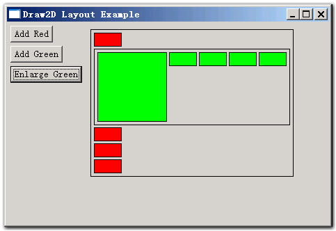
一个Layout的例子,点此下载,截图如下。
搬家前链接:https://www.cnblogs.com/bjzhanghao/archive/2006/09/05/495747.html
一些朋友无法直接访问国际网来连接到eclipse.org的cvs服务器,这里是常见的几个例子的打包下载:
搬家前链接:https://www.cnblogs.com/bjzhanghao/archive/2006/08/11/474249.html
在ecore模型里可以详细的定义各种类型、属性和方法,但对于像“每个类别里至少有两种产品”这样的限制就无能为力了。为此,EMF提供了一套验证框架(Validator Framework)用于解决这个问题,在ecore文件里特定的方法可以被识别为验证方法并生成用于验证的代码。
还是以shop模型为例,假设要求“每个类别里至少有两种产品”,我们需要在shop.ecore里添加一个名为validateProductsCount的验证方法,如图1所示。验证方法的返回类型是要具有两个参数:第一个是EDiagnosticChain类型,第二个是EMap类型,参数的名称没有特别要求,但这两个参数的顺序不能交换。
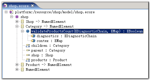
图1 新增的验证方法
接下来,通过shop.genmodel重新生成一遍代码(如果还没有shop.genmodel文件,通过New -> EMF Model创建一个),注意没有必要reload这个genmodel文件。通过比较添加验证方法前后的代码,可以发现EMF在util包里多生成了一个名为ShopValidator.java的文件;同时,在CategoryImpl的validateProductsCount()方法里的代码如下所示:
/**
 * <!-- begin-user-doc -->
 * <!-- end-user-doc -->
 * @generated
 */
public boolean validateProductsCount(DiagnosticChain diagnostics, Map contex) {
    // TODO: implement this method
    // -> specify the condition that violates the invariant
    // -> verify the details of the diagnostic, including severity and message
    // Ensure that you remove @generated or mark it @generated NOT
    if (false) {
        if (diagnostics != null) {
            diagnostics.add
                (new BasicDiagnostic
                    (Diagnostic.ERROR,
                     ShopValidator.DIAGNOSTIC_SOURCE,
                     ShopValidator.CATEGORY__VALIDATE_PRODUCTS_COUNT,
                     EcorePlugin.INSTANCE.getString("_UI_GenericInvariant_diagnostic", new Object[] { "validateProductsCount", EObjectValidator.getObjectLabel(this, contex) }),
                     new Object [] { this }));
        }
        return false;
    }
    return true;
}有别于普通方法的实现(简单的抛出一个UnsupportedOperationException异常)。由于这段代码是被if(false){...}包围的,所以如果不进行定制,则里面的内容永远不会被执行,被包围代码的功能是将验证错误记录下来以便统一报告。现在,我们要做的就是修改这个条件,来告诉EMF什么时候运行里面的代码,如下所示:
/**
 * <!-- begin-user-doc -->
 * <!-- end-user-doc -->
 * @generated NOT
 */
public boolean validateProductsCount(DiagnosticChain diagnostics, Map contex) {
    // 我们修改了验证条件
    if (getProducts().size() < 2) {
        if (diagnostics != null) {
            diagnostics.add
                (new BasicDiagnostic
                    (Diagnostic.ERROR,
                     ShopValidator.DIAGNOSTIC_SOURCE,
                     ShopValidator.CATEGORY__VALIDATE_PRODUCTS_COUNT,
                     EcorePlugin.INSTANCE.getString("_UI_GenericInvariant_diagnostic", new Object[] { "validateProductsCount", EObjectValidator.getObjectLabel(this, contex) }),
                     new Object [] { this }));
        }
        return false;
    }
    return true;
}
因为我们要实现的验证条件很简单,所以代码的改动也很少,还是注意不要忘记修改注释中的@generated标记。现在可以运行我们的shop编辑器了,在一个只包含一种产品(Product)的类别(Category)上按右键,选择弹出菜单里的“Validate”命令,就会得到如图2所示的提示信息。
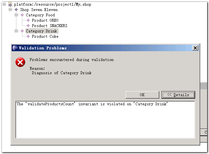
图2 模型未通过验证
通过修改代码的方式表达模型的限制条件是很直观,不过当条件又多又不确定的时候,直接在ecore文件里集中的表达这些条件也许更方便管理,而且Java代码甚至不需要重新生成和编译。Eclipse网站上的这篇文章“Implementing Model Integrity in EMF with EMFT OCL”通过自定义JET模板实现了这个功能,有兴趣的朋友不妨试试。
补充另一种让EMF生成Validate代码的方法:在ecore模型里需要验证的EClass下建立一个EAnnotation,其source属性为“http://www.eclipse.org/emf/2002/Ecore”;然后在这个EAnnotation下建立key为“constraints”的Details Entry,value属性指定为想要的constraint名字,如果要定义多个constraint,则每个名字之间用空格分隔(格式见EcoreUtil#setConstraints()),如图3所示。这样,EMF就会在util包里生成XXXValidator.java文件,以及相应的验证方法,这些方法的代码和上面第一段嗲吗是类似的,同样需要自己修改if语句里的条件。
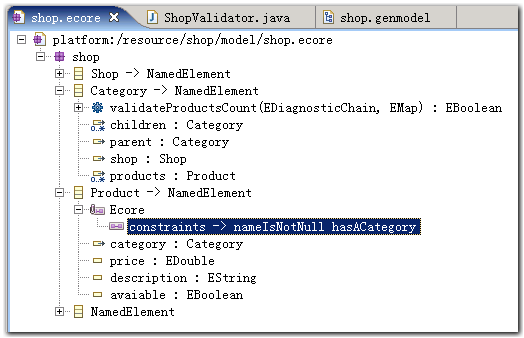
图3 在ecore模型里添加EAnnotation以生成验证代码
搬家前链接:https://www.cnblogs.com/bjzhanghao/archive/2006/08/09/472607.html
在Aimd同学的代码里看到的,得到相对一个Plugin路径的方法,赶紧记下来:
FileLocator.toFileURL(Platform.getBundle("plugin.id").getEntry("/images")).getFile();注意:需要Eclipse 3.2版本
Update(2007/01/19): 这里还有其他一些路径的获得方法:http://www.blogjava.net/hopeshared/archive/2005/12/20/24798.html
Update(2008/11/20): 从IResource得到java.io.File的方法:IResource#getLocation().toFile()
搬家前链接:https://www.cnblogs.com/bjzhanghao/archive/2006/07/19/454980.html
除了利用Eclipse提供的属性视图以外,GEF应用程序里当然也可以通过弹出对话框修改模型信息。
要实现双击一个节点打开对话框,在NodePart里要增加的代码如下:
public void performRequest(Request req) {
    if(req.getType().equals(RequestConstants.REQ_OPEN)){
        MessageDialog.openInformation(getViewer().getControl().getShell(),"Gef Practice","A Dialog");
    }
}
作为例子,上面这段代码只打开一个显示信息的对话框,你可以替换成自己实现的对话框显示/修改节点信息。
在CreateNodeCommand里增加下面的代码,可以在每次创建一个节点时通过对话框指定节点的名称:
public void execute() {
    InputDialog dlg = new InputDialog(shell, "Gef Practice", "New node's name:", "Node", null);
    if (Window.OK == dlg.open()) {
        this.node.setName(dlg.getValue());
    }
    this.diagram.addNode(this.node);
}
因为打开对话框时需要用到Shell,所以要在CreateNodeCommand里增加一个Shell类型的成员变量,并在DiagramLayoutEditPolicy里创建CreateNodeCommand时把一个shell实例传递给它。
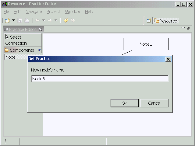
创建节点时先弹出对话框
点此下载工程,此工程修改自GEF应用实例中的GefPractice,目标文件的扩展名改为.gefpracticedlg。
搬家前链接:https://www.cnblogs.com/bjzhanghao/archive/2006/07/07/445603.html
利用自动布局功能,我们可以把本来不包含图形信息的文件以图形化的方式展示出来,典型的例子比如将一组Java接口反向工程为类图,那么图中每个图元的坐标应该必须都是自动生成的。GEF里提供了DirectedGraphLayout类用来实现自动布局功能,下面介绍一下怎样在程序里使用它。
DirectedGraphLayout提供的visit()方法接受一个org.eclipse.draw2d.graph.DirectedGraph实例,它遍历这个有向图的所有节点和边,并按照它自己的算法计算出每个节点布局后的新位置。所以在使用它布局画布上的图元分为两个步骤:1、构造有向图,2、将布局信息应用到图元。
还是以gefpractice为基础,我们在主工具条上增加了一个自动布局按钮,当用户按下它时自动布局编辑器里的图形,再次按下时恢复以前的布局。为了完成步骤1,我们要在DiagramPart里添加以下两个方法:
/**
 * 将图元(NodePart)转换为节点(Node)到有向图
 * @param graph
 * @param map
 */
public void contributeNodesToGraph(DirectedGraph graph, Map map) {
    for (int i = 0; i < getChildren().size(); i++) {
        NodePart node = (NodePart)getChildren().get(i);
        org.eclipse.draw2d.graph.Node n = new org.eclipse.draw2d.graph.Node(node);
        n.width = node.getFigure().getPreferredSize().width;
        n.height = node.getFigure().getPreferredSize().height;
        n.setPadding(new Insets(10,8,10,12));
        map.put(node, n);
        graph.nodes.add(n);
    }
}

/**
 * 将连接(ConnectionPart)转换为边(Edge)添加到有向图
 * @param graph
 * @param map
 */
public void contributeEdgesToGraph(DirectedGraph graph, Map map) {
    for (int i = 0; i < getChildren().size(); i++) {
        NodePart node = (NodePart)children.get(i);
        List outgoing = node.getSourceConnections();
        for (int j = 0; j < outgoing.size(); j++) {
            ConnectionPart conn = (ConnectionPart)outgoing.get(j);
            Node source = (Node)map.get(conn.getSource());
            Node target = (Node)map.get(conn.getTarget());
            Edge e = new Edge(conn, source, target);
            e.weight = 2;
            graph.edges.add(e);
            map.put(conn, e);
        }
    }
}
要实现步骤2,在DiagramPart里添加下面这个方法:
/**
 * 利用布局后的有向图里节点的位置信息重新定位画布上的图元
 * @param graph
 * @param map
 */
protected void applyGraphResults(DirectedGraph graph, Map map) {
    for (int i = 0; i < getChildren().size(); i++) {
        NodePart node = (NodePart)getChildren().get(i);
        Node n = (Node)map.get(node);
        node.getFigure().setBounds(new Rectangle(n.x, n.y, n.width, n.height));
    }
}为了以最少的代码说明问题,上面的方法里只是简单的移动了图形,而没有改变模型里Node的属性值,在大多情况下这里使用一个CompoundCommand对模型进行修改更为合适,这样用户不仅可以撤消(Undo)这个自动布局操作,还可以在重新打开文件时看到关闭前的样子。注意,DirectedGraphLayout是不保证每次布局都得到完全相同的结果的。
因为Draw2D里是用LayoutManager管理布局的,而DirectedGraphLayout只是对布局算法的一个包装,所以我们还要创建一个布局类。GraphLayoutManager调用我们在上面已经添加的那几个方法生成有向图(partsToNodes变量维护了编辑器图元到有向图图元的映射),利用DirectedGraphLayout对这个有向图布局,再把结果应用到编辑器里图元。如下所示:
class GraphLayoutManager extends AbstractLayout {

    private DiagramPart diagram;

    GraphLayoutManager(DiagramPart diagram) {
        this.diagram = diagram;
    }

    protected Dimension calculatePreferredSize(IFigure container, int wHint, int hHint) {
        container.validate();
        List children = container.getChildren();
        Rectangle result = new Rectangle().setLocation(container.getClientArea().getLocation());
        for (int i = 0; i < children.size(); i++)
            result.union(((IFigure) children.get(i)).getBounds());
        result.resize(container.getInsets().getWidth(), container.getInsets().getHeight());
        return result.getSize();
    }

    public void layout(IFigure container) {
        DirectedGraph graph = new DirectedGraph();
        Map partsToNodes = new HashMap();
        diagram.contributeNodesToGraph(graph, partsToNodes);
        diagram.contributeEdgesToGraph(graph, partsToNodes);
        new DirectedGraphLayout().visit(graph);
        diagram.applyGraphResults(graph, partsToNodes);
    }

}
当用户按下自动布局按钮时,只要设置DiagramPart对应的图形的布局管理器为GraphLayoutManager就可以实现自动布局了,布局的结果如图所示。
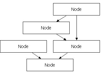
自动布局的结果
最后有几点需要说明:
1、DirectedGraphLayout只能对连通的有向图进行布局,否则会产生异常graph is not fully connected,参考Eclipse.org文章Building a Database Schema Diagram Editor中使用的NodeJoiningDirectedGraphLayout可以解决这个问题;
2、如果要对具有嵌套关系的有向图自动布局,应使用SubGraph和CompoundDirectedGraphLayout;
3、这个版本的gefpractice在自动布局后,没有对连接线进行处理,所以可能会出现连接线穿过图元的情况,这个问题和上一个问题都可以参考GEF提供的flow例子解决。
Update(2007/4/9):如果diagram是放在ScrollPane里的,则要修改一下applyGraphResults()方法,增加container作为参数以使整个diagram能正确滚动。
protected void applyGraphResults(DirectedGraph graph, Map map, IFigure container) {
    for (Iterator iterator = this.nodeParts.iterator(); iterator.hasNext();) {
        NodePart element = (NodePart) iterator.next();
        Node n = (Node) map.get(element);
        Rectangle containerBounds=container.getBounds();
        Rectangle elementBounds=new Rectangle(n.x, n.y, n.width, n.height);
        element.getFigure().setBounds(elementBounds.translate(containerBounds.getLocation()));
    }
}点此下载工程,此工程修改自GEF应用实例中的GefPractice,目标文件的扩展名改为.gefpracticeal。
搬家前链接:https://www.cnblogs.com/bjzhanghao/archive/2006/07/02/440896.html
现在假设要把原来GefPractice例子里的矩形图元节点换成用椭圆形表示,都需要做哪些改动呢?很显然,首先要把原来继承RectangleFigure的NodeFigure类改为继承Ellipse类:
public class NodeFigure extends Ellipse {
    ...
}
这样修改后可以看到编辑器中的图元已经变成椭圆形了。但如果用户点选一个图元,表示选中的边框(选择框)仍然是矩形的,如图1所示:

图1 椭圆形的节点和矩形选择框
如果觉得矩形的选择框不太协调,可以通过覆盖DiagramLayoutEditPolicy的createChildEditPolicy()方法修改。缺省情况下这个方法返回一个ResizableEditPolicy,我们要定义自己的子类(EllipseResizableEditPolicy)来替代它作为返回值。
EllipseResizableEditPolicy里需要覆盖ResizableEditPolicy的两个方法。第一个是createSelectionHandles()方法,它决定“控制柄”(ResizeHandle)和“选择框”(MoveHandle)的相关情况,我们的实现如下:
protected List createSelectionHandles() {
    List list = new ArrayList();
    //添加选择框
    //ResizableHandleKit.addMoveHandle((GraphicalEditPart) getHost(), list);
    list.add(new MoveHandle((GraphicalEditPart) getHost()) {
        protected void initialize() {
            super.initialize();
            setBorder(new LineBorder(1) {
                public void paint(IFigure figure, Graphics graphics, Insets insets) {
                    tempRect.setBounds(getPaintRectangle(figure, insets));
                    if (getWidth() % 2 == 1) {
                        tempRect.width--;
                        tempRect.height--;
                    }
                    tempRect.shrink(getWidth() / 2, getWidth() / 2);
                    graphics.setLineWidth(getWidth());
                    if (getColor() != null)
                        graphics.setForegroundColor(getColor());
                    //用椭圆形替代矩形
                    //graphics.drawRectangle(tempRect);
                    graphics.drawOval(tempRect);
                }
            });
        }
    });

    //添加控制柄
    ResizableHandleKit.addHandle((GraphicalEditPart) getHost(), list, PositionConstants.EAST);
    ResizableHandleKit.addHandle((GraphicalEditPart) getHost(), list, PositionConstants.SOUTH);
    ResizableHandleKit.addHandle((GraphicalEditPart) getHost(), list, PositionConstants.WEST);
    ResizableHandleKit.addHandle((GraphicalEditPart) getHost(), list, PositionConstants.NORTH);
    return list;
}第二个是createDragSourceFeedbackFigure()方法,它决定用户拖动图形时,随鼠标移动的半透明图形(即“鬼影”)的形状和颜色,因此我们覆盖这个方法以显示椭圆形的鬼影。
protected IFigure createDragSourceFeedbackFigure() {
    //用椭圆替代矩形
    //RectangleFigure r = new RectangleFigure();
    Ellipse r = new Ellipse();
    FigureUtilities.makeGhostShape(r);
    r.setLineStyle(Graphics.LINE_DOT);
    r.setForegroundColor(ColorConstants.white);
    r.setBounds(getInitialFeedbackBounds());
    addFeedback(r);
    return r;
}
经过以上这些修改,可以看到选择框和鬼影都是椭圆的了,如图2所示。
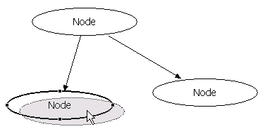
图2 与节点形状相同的选择框和鬼影
点此下载工程,此工程修改自GEF应用实例中的GefPractice,目标文件的扩展名改为.gefpracticeel。
搬家前链接:https://www.cnblogs.com/bjzhanghao/archive/2006/06/26/436455.html
在类图里能看到一些对象具有对自己的引用,通常这些引用用于表达树状结构,即父子节点都是同一类对象。用GEF绘制这样的连接线一般是通过转折点(Bendpoint)实现的,如果你的GEF应用程序里还不能使用Bendpoint,请按照上一篇介绍的步骤添加对Bendpoint的支持。
原先我们的GefPractice应用程序是不允许一条连接线的起点和终点都是同一个图形的,因为这样会导致连接线缩成一个点隐藏在图形下方,用户并不知道它的存在。当时我们在CreateConnectionCommand类的canExecute()方法里进行了如下判断:
public boolean canExecute() {
    if (source.equals(target))
        return false;
    ...
}因此现在首先要把这两句删除。然后在execute()方法里对自身连接的这种情况稍做处理,处理的方法是给这条连接线在适当位置增加三个Bendpoint,你也可以根据想要的连接线形状修改Bendpoint的数目和位置。
public void execute() {
    connection = new Connection(source, target);
    if (source == target) {
        //The start and end points of our connection are both at the center of the rectangle,
        //so the two relative dimensions are equal.
        ConnectionBendpoint cbp = new ConnectionBendpoint();
        cbp.setRelativeDimensions(new Dimension(0, -60), new Dimension(0, -60));
        connection.addBendpoint(0, cbp);
        ConnectionBendpoint cbp2 = new ConnectionBendpoint();
        cbp2.setRelativeDimensions(new Dimension(100, -60), new Dimension(100, -60));
        connection.addBendpoint(1, cbp2);
        ConnectionBendpoint cbp3 = new ConnectionBendpoint();
        cbp3.setRelativeDimensions(new Dimension(100, 0), new Dimension(100, 0));
        connection.addBendpoint(2, cbp3);
    }
}
现在用户只要选择连接工具,然后在一个节点上连续点两下就可以创建自身连接了,如下图所示。
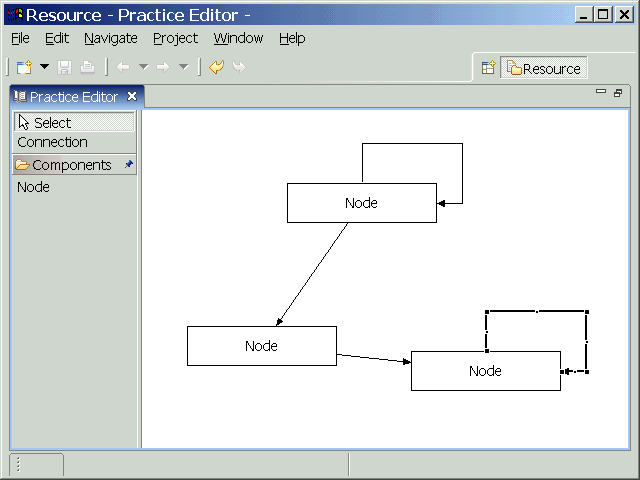
图:自身连接
点此下载工程,此工程修改自GEF常见问题2中的GefPractice-bp,目标文件扩展名为.gefpracticesc。
搬家前链接:https://www.cnblogs.com/bjzhanghao/archive/2006/06/22/432553.html